目录
- 1. Overview
- 2. Terms and Definitions
- 3. Version
- 4. Production Data
- 5. Output Current
- 6. Channel Mode
- 7. Operating Mode
- 8. Short Address
- 9. Dimming Curve
- 10. Color LED Correction
- 11. Dali Parameters
- 12. Constant Lumen Output(CLO)
- 13. Emergency Lighting(EL)
- 14. Push Dim and Corridor Function
- 15. Over Temperature Protection(OTP)
- 16. Power On Fade
- 17. Integrated Dali Power Supply(IDPS)
- 18. OEM Data
- 19. Luminare Maintenance Data
- 20. OEM Key
- 21. Command
- 22. Revision History
1. Overview
This document describes software parameters definitions. These parameters can be read or written by DALI / NFC based on permission.
Standards Compliant:
- DALI: IEC62386-101, 102, 105, 207(DT6), 209(DT8), 250, 251, 252, 253
2. Terms and Definitions
| Name | Description |
| PHM | Physical Minimum Level according to DALI102 |
| MSB | Most Significant Byte |
| LSB | Least Significant Byte |
| CCT | Correlated Color Temperature |
3. Version
Firmware version is formated by Major.Minor.Build.
Hardware version is formated by Major.Minor.
| Name | Length | Default | Range |
| Firmware Ver Major | 1byte | Product Specific | [1, 255] |
| Firmware Ver Minor | 1byte | Product Specific | [0, 255] |
| Firmware Build Ver | 2byte | Product Specific | [0-0xFFFF] |
| Hardware Ver Major | 1byte | 1 | [1, 255] |
| Hardware Ver Minor | 1byte | 0 | [0, 255] |
4. Production Data
Below parameters are supported.
| Name | Length | Default | Range |
| Identification Number | 8 bytes | 0xFF..FF | [0-0xFF..FF] |
Identification Number is 20 digits, after converting from 8 bytes HEX value. 0 or 0xFFFFFFFFFFFFFFFF(18446744073709551615) is empty.
| Digit20-12 | Digit11-10 | Digit9-8 | Digit7-0 |
| Article Number | Year | Week | Incremental Number |
Incremental Number is a 8 digits unique number for each Year and Week. It has range 0~99,999,999.
Year is last 2 digits of calenda year. For example, 21 means 2021.
Week is week number of calenda week. For example 04 means 4th week.
Article Number is a 9 digits value, unique for each product article. It has range 0~184,467,439.
5. Output Current
Output current when 100% level can be configured.
Below parameters are supported.
| Description | Length | Default | Range |
| Current Set | 2bytes | Product Specific | [0,0xFFFF] |
| CH2 Current Set | 2bytes | Product Specific | [0,0xFFFF] |
Current Set/CH2 Current Set:
- 0: Current Set by Analogue(DIP Switch, Resistor...)
- 1-65534: unit is mA
- 65535: Not supported
6. Channel Mode
Below parameters are supported.
| Name | Length | Default | Range |
| Channel Mode | 1 byte | Product Specific | [0,8] |
Channel Mode: Below modes are supported
- 0x00: 1x207
- 0x01: 2x207
- 0x02: 3x207
- 0x03: 4x207
- 0x04: 1x209 Tc
- 0x05: 2x209 Tc
- 0x06: 1x209 RGBWAF
- 0x07: 1x209 TC+RGBWAF+XY
- 0x08: 1x207+1x209 Tc
7. Operating Mode
Below parameters are supported.
| Name | Length | Default | Range |
| Operating Mode | 1byte | Product Specific | [0, 0x80-0x82] |
Default Operating Mode:
- 0: DALI Standard Mode
- 0x80: Auto Mode
- 0x81: Push Dim
- 0x82: Corridor
8. Short Address
DALI Short Address can be fast set by NFC
| Name | Length | Default | Range |
| Short Address | 1byte | 0xFF | [0-63,0xFF] |
Short Address: Up to 64 short addresses. 0xFF means Unaddressed.
9. Dimming Curve
DALI dimming curvers are supported, including Logarithmic and Linear curve.
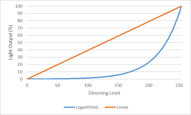
Logarithmic dimming curve can be calculated by
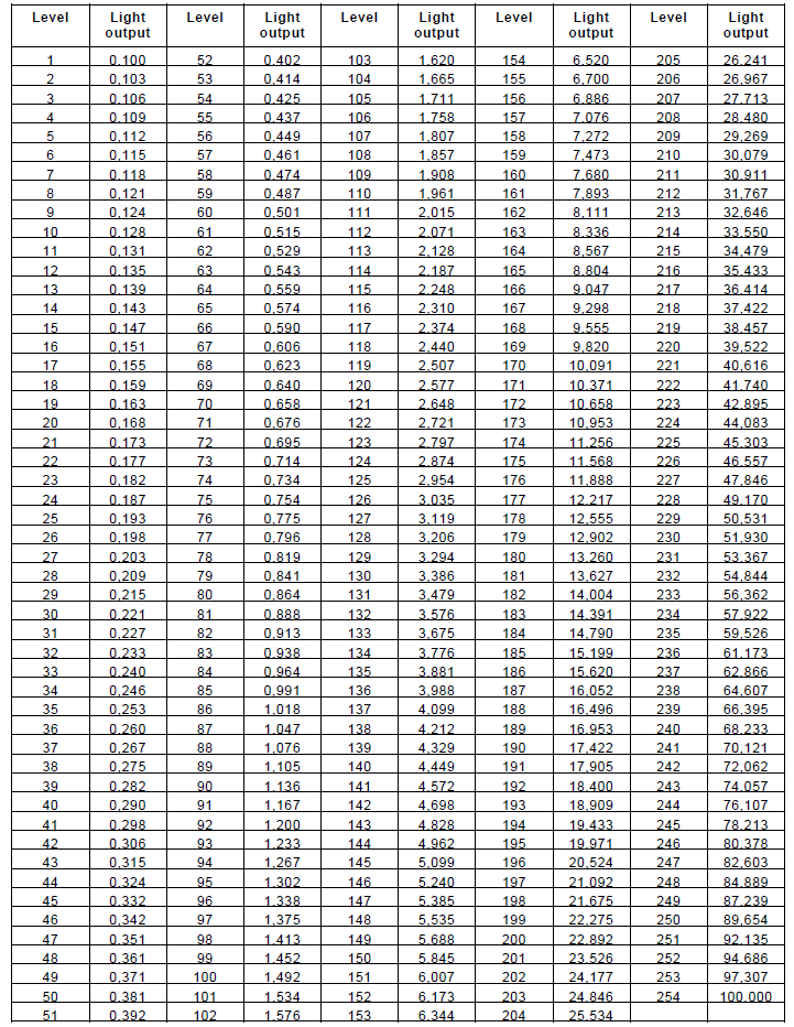
LightOutput = 10(level-1)*3/253 -1 % when level > 0
A table of logarithmic dimming curve is as following.
Linear dimming curve can be calculated by
LightOutput = 100 * Level / 254
Below parameters are supported.
| Name | Length | Default | Range |
| Dimming Curve | 1byte | 0 | [0,1] |
Dimming Curve:
- 0: Logarithmic dimming curve
- 1: Linear dimming curve
10. Color LED Correction
Color temperature can be approximated using just a pair of xy coordinates from CIE 1931.
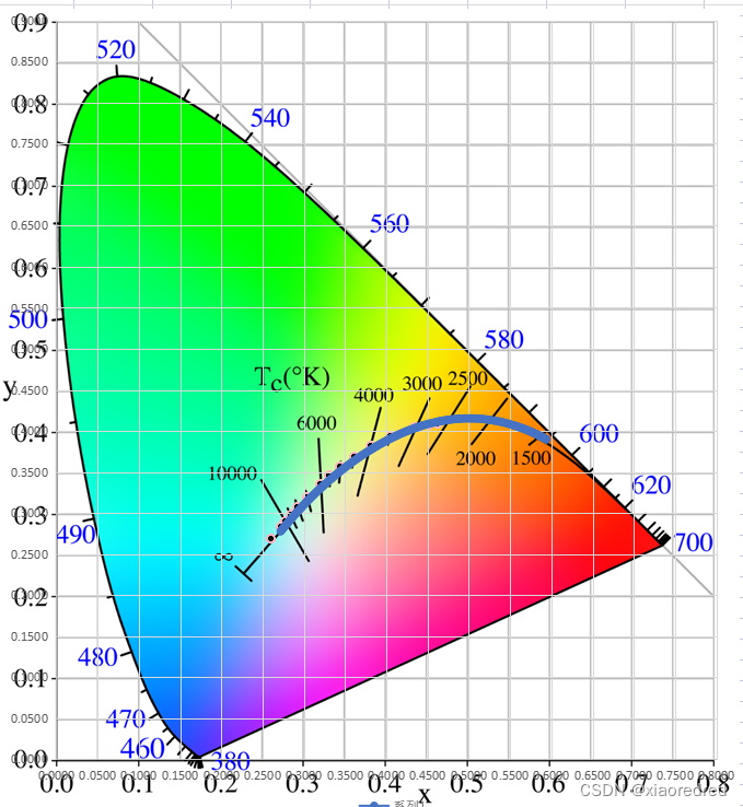
2 channels LED color information shall be written. These information can be from LED module specification. Color Coordinate and Flux value of each color are necessary. The driver software will automaticall calculate target mixed color. This will be more accurate and no need to manually adjust to correct the color.
10.1 Color caculation
For CCT, the unit is Mirek, which can be calculated by below fomular, T is color temperature.
Mirek = 1000,000 / T
Below formula(McCamy's approximation) is used to calculate CCT by CIE 1931 xy values:
n = (x-0.3320)/(0.1858-y);
CCT = 437*n^3 + 3601*n^2 + 6861*n + 5517
Lookup table to get CIE 1931 xy values from CCT value can be got from CSV format or JSON format
10.2 Parameters
Below parameters are supported.
| Name | Length | Default | Range |
| CH1 LED Flux | 2bytes | 1000 | [0-0xFFFF] |
| CH1 LED Color Coordinate X | 2bytes | 0xFFFF | [0-0xFFFF] |
| CH1 LED Color Coordinate Y | 2bytes | 0xFFFF | [0-0xFFFF] |
| CH2 LED Flux | 2bytes | 1000 | [0-0xFFFF] |
| CH2 LED Color Coordinate X | 2bytes | 0xFFFF | [0-0xFFFF] |
| CH2 LED Color Coordinate Y | 2bytes | 0xFFFF | [0-0xFFFF] |
CHx LED Flux: The value is lumen output of LED channel. 0xFFFF means not supported.
CHx LED Color Coordinate X: The value is CIE1931 coordinate value multiplexed by 65535. For example, if Coordinate X is 0.351, value is 0.351*65535=23002. 0xFFFF means not supported.
CHx LED Color Coordinate Y: The value is CIE1931 coordinate value multiplexed by 65535, same as Coordinate X. 0xFFFF means not supported
11. Dali Parameters
This feature follows DALI standard IEC62386-102 Ed2.
Level is according to Dimming Curve Level
Below parameters are supported.
| Description | Length | Default | Range |
| Power On Level | 1byte | 0xFE | [0,0xFF] |
| System Failure Level | 1byte | 0xFE | [0,0xFF] |
| Min Level | 1byte | PHM | [PHM,Max Level] |
| Max Level | 1byte | 0xFE | [Min Level,0xFE] |
| Extended Fade Time | 1byte | 0 | [0,0x4F] |
| Fade | 1byte | 0x07 | [0,0xFF] |
| Group | 2bytes | 0 | [0,0xFF FF] |
| Scene0 Level | 1byte | 0 | [0,0xFF] |
| ... | |||
| Scene15 Level | 1byte | 0 | [0,0xFF] |
| Power On CCT | 2bytes | Product Specific | [2000-7000,0xFFFF] |
| System Failure CCT | 2bytes | Product Specific | [2000-7000,0xFFFF] |
| Coolest CCT | 2bytes | 7000 | [2000-7000,0xFFFF] |
| Warmest CCT | 2bytes | 2000K | [2000-7000,0xFFFF] |
| Scene0 CCT | 2bytes | 0xFFFF | [2000-7000,0xFFFF] |
| ... | |||
| Scene15 CCT | 2bytes | 0xFFFF | [2000-7000,0xFFFF] |
Power On Level: Dali level when driver powered on. 0xFF means last light level.
System Failure Level: Dali level when DALI bus has failure. 0xFF means no action when failure detected.
Min Level: Minimum level for DALI dimming. It has a range of PHM to Max Level
Max Level: Maximum level for DALI dimming. It has a range of Min Level to 254
Extended Fade Time: this is following DALI102 extended fade time, specified as following, includeing fade time base value and multiplier. Fade time is calculated by below fomular:
Fade Time = (Base Value+1)*Multiplier
| Bit7-4 | Bit3-0 |
| Multiplier | Base Value |
Base Value has range 0-15
Multiplier is specified as following.
- 0b0000: 0s
- 0b0001: 0.1s
- 0b0010: 1s
- 0b0011: 10s
- 0b0100: 1min
Fade: this is following DALI102 fade time and fade rate,
| Bit7-4 | Bit3-0 |
| Fade Time | Fade Rate |
Fade Time: If Fade time is 0, then Extended Fade Time is used. Otherwise is specified as following:
| Value |
Fade Time s
|
Value |
Fade Time s
|
Value |
Fade Time s
|
| 1 | 0.7 | 6 | 4 | 11 | 22.6 |
| 2 | 1 | 7 | 5.7 | 12 | 32 |
| 3 | 1.4 | 8 | 8 | 13 | 45.3 |
| 4 | 2 | 9 | 11.3 | 14 | 64 |
| 5 | 2.8 | 10 | 16 | 15 | 90.5 |
Fade Rate is specified as following:
| Value |
Fade Rate
steps/s
|
Value |
Fade Rate
steps/s
|
Value |
Fade Rate
steps/s
|
| 1 | 358 | 6 | 63.3 | 11 | 11.2 |
| 2 | 253 | 7 | 44.7 | 12 | 7.9 |
| 3 | 179 | 8 | 31.6 | 13 | 5.6 |
| 4 | 127 | 9 | 22.4 | 14 | 4.0 |
| 5 | 89.4 | 10 | 15.8 | 15 | 2.8 |
Group: Group membership. BitX High means device is in GroupX. X can be from 0 to 15.
SceneX Level: Scene level recored. The recorded level is DALI Level. 0xFF means no level recoreded.
SceneX CCT: unit is Mirek accoridng to CCT description. 0xFF means Empty
12. Constant Lumen Output(CLO)
Constant Lumen Output (CLO) is used to compensate the lumen decrease over LEDs lifetime. The degradation of the LED can be compensated by increasing the LED current over lifetime according to a LED dependent aging model. The aging function of the LED is modeled by a linear model over time with maximum eight reference points. The actual output level percentage will be calculated automatically by linear interpolation between two neighbored reference points.
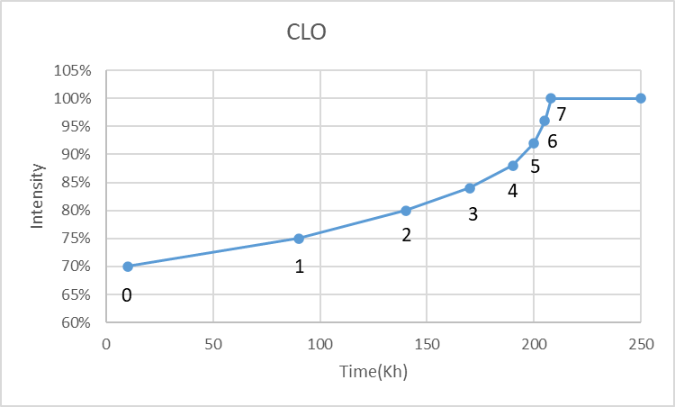
Below parameters are supported.
| Name | Length | Default | Range |
| CLO Configure | 1 byte | 1 | [1, 3] |
| CLO Intensity0 | 1 byte | 0xFF | [1-100,0xFF] |
| CLO Time1 | 1 byte | 0xFF | [1-0xFF] |
| CLO Intensity1 | 1 byte | 0xFF | [1-100,0xFF] |
| CLO Time2 | 1 byte | 0xFF | [1-0xFF] |
| CLO Intensity2 | 1 byte | 0xFF | [1-100,0xFF] |
| CLO Time3 | 1 byte | 0xFF | [1-0xFF] |
| CLO Intensity3 | 1 byte | 0xFF | [1-100,0xFF] |
| CLO Time4 | 1 byte | 0xFF | [1-0xFF] |
| CLO Intensity4 | 1 byte | 0xFF | [1-100,0xFF] |
| CLO Time5 | 1 byte | 0xFF | [1-0xFF] |
| CLO Intensity5 | 1 byte | 0xFF | [1-100,0xFF] |
| CLO Time6 | 1 byte | 0xFF | [1-0xFF] |
| CLO Intensity6 | 1 byte | 0xFF | [1-100,0xFF] |
| CLO Time7 | 1 byte | 0xFF | [1-0xFF] |
| CLO Intensity7 | 1 byte | 0xFF | [1-100,0xFF] |
| CLO Operating Time | 2 bytes | 0 | [0-63750,0xFFFF] |
CLO Configure:
| Bit7-2 | Bit1 | Bit0 |
| Reserve | EndOfLife | Enable |
CLO Time: unit is 0.5KHour. Maximum time is 127.5Khour
CLO Intensity0-7: unit is 1%.
CLO Operating Time: unit is 2hour. Maximum time is 127.5Khour
Enable: Value is readonly, always 1.
EndOfLife: If supporting EndOfLife feature, and set to 1, the driver will blink within first 2sec for every startup.
13. Emergency Lighting(EL)
When AC power disappearing situation happened, mains voltage can be switched to emergency battery in emergency system, and the driver may not output 100% but to a defined level, thus to save energy.
For a Color Temperature supporting led driver, emergency color temperature is also able to configure.
| Name | Length | Default | Range |
| Emergency Configure | 1byte | 1 | [0,1] |
| Emergency Level | 1byte | 185 | [PHM-0xFF] |
| Emergency CCT | 2bytes | 0xFF FF | [142-500,0xFFFF] |
Emergency Configure:
- 0: Disable, dimming at DC
- 1: Enable, emergency at DC
Emergency Level: 0xFF means Not Supported. Level is according to Logarithmic Dimming Curve Level.
Emergency CCT: unit is Mirek accoridng to CCT description. 0xFFFF means No Change
14. Push Dim and Corridor Function
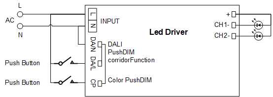
By connecting AC switch(push button or motion sensor) to DA port in series, this can provide an easy way to ON/OFF/DIM of a LED driver without connecting DALI. It is also possible to connecting more than one LED drivers in parallel with same AC switch to control together.
14.1 Wiring Connection
For one channel output LED driver, detail diagram is as following.

It is also possible to dim color of a 2 channel led driver by adding one more AC switch to CP port. Detail diagram is as following.
14.2 Push Dim
Push Dim has 2 dimming speed. By default is 3sec from highest to lowest dim level. After changing to low speed mode, during will change to 6sec.
Color Push has 2 dimming speed. By default is 2.5sec from coolest to warmest color temperature. After changing to low speed mode, during will change to 5sec.
Power on level will be the level when last AC dropped. If it was switched off when last AC dropped, it will stay switched off.
| Operation | Contact Duration | Push Dim | Color Push Dim |
| Ignore | <40ms | Discard Push | Discard Push |
| Short Press | 40ms~500ms | Toggle ON/OFF | Switch to next Color Scene |
| Long Press | 500ms~10s | Dim UP/DOWN | Dim Cooler/Warmer |
| Double Click when ON* | 2times within 500ms | Store current level | Store current color |
| Double Click when OFF* | 2times within 500ms | Remove current level | Remove current color |
| Reset Press | >10s | Syncronize drivers | Syncronize drivers |
| Low Speed Press | >20s | Change to low speed | Change to low speed |
| Corridor Press* | >120s | Go To Corridor | |
| PushDim Press* | 5times within 3 sec | Go to PushDim, Reset to default | Reset to default |
Note:
* Some products may not support these operations
There are 9 preset scenes. Short press color push button will switch to next color scene. After 9st scene is triggered, it will turn to 1st scene.
| Scene | Color Temperature | Scene | Color Temperature | Scene | Color Temperature |
| 1 | 2700K | 4 | 4000K(default) | 7 | 5500K |
| 2 | 3000K | 5 | 4500K | 8 | 6000K |
| 3 | 3500K | 6 | 5000K | 9 | 6500K |
Synchronizing of PushDim:
If the installation has many drivers, the dimming direction of the newly connected drivers may be different from that of those already connected. To solve this problem a synchronization possibility is built into the drivers and can be called upon at any time. There are 2 ways to synchronize.
- Reset Press will make all drivers synchronized. Dim level will change to 50%. But this may not work if combining use with other brands drivers like OSRAM.
- A sequence of LONG-SHORT-LONG press, all drivers will be synchronized.
1. Long press: all drivers are switched ON
2. Short press: all drivers are switched OFF
3. Long press: all drivers are switched ON at min level, and fading up
14.3 Corridor Function
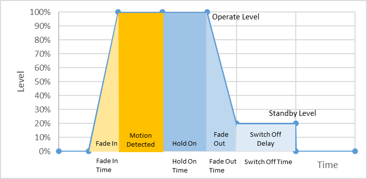
Corridor Function controls the light level when presence is detected by a simple on/off mains sensor. It ensures that energy is conserved by reducing light output when no movement is detected. This feature helps lower electricity consumption and contributes to long-term cost savings.
When there is mains signal detected, light level will fade to Operate Level. After motion is gone, motion sensor will not output mains signal. Then driver will wait a Hold On time, then starts to fade out to Derate Level. If no further motion detected, driver will shutdown. For any moment, if there is motion detected, the driver will fade to Operate Level with Fade In Time, and operate this sequence again.
| Name | Length | Default | Range |
| Push Configure | 1byte | Product Specific | [0-7] |
| Push Stored Level | 1byte | 0xFF | [0, PHM-254,0xFF] |
| Color Push Stored CCT | 2bytes | 0xFF FF | [0-0xFF FF] |
| Corridor Operate Level | 1byte | 254(100%) | [0, PHM-254] |
| Corridor Standby Level | 1byte | 170(10%) | [0, PHM-254] |
| Corridor Fade In Time | 1byte | 0 | [0-254] |
| Corridor Hold On Time | 1byte | 12(120s) | [0-254] |
| Corridor Fade Out Time | 1byte | 0x32(30s) | [0-254] |
| Corridor Switch Off Time | 1byte | 0xFF | [0-254, 0xFF] |
Push Configure:
| Bit7-3 | Bit2 | Bit1 | Bit0 |
| Reserve | Color Push Enable | Corridor Enable | Push Dim Enable |
Bit2-0:
- 0: disabled
- 1: enabled
Supported options:
- PushDim Enable
- PushDim + Corridor Enable
- PushDim + ColorPush Enable
- PushDim + Corridor + ColorPush Enable
Push Stored Level: 0xFF means no level stored. Level is according to Dimming Curve Level
Color Push Stored CCT: unit is Mirek accoridng to CCT description. 0xFF FF means no color stored.
Corridor Operate Level and Corridor Standby Level: Level is according to Dimming Curve Level
Corridor Fade In Time and Corridor Fade Out Time: Fade Time is according to Fade Time.
Corridor Hold On Time: unit is 10s.
Corridor Switch Off Time: unit is 10s. 0xFF means never switching off.
15. Over Temperature Protection(OTP)
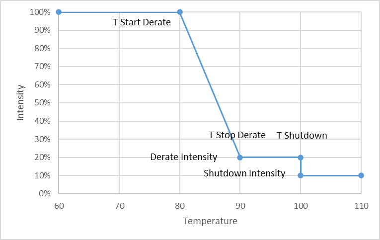
2 Temperature protections are supported. One is for led driver itself, the other is for led luminaire. Over Temperature Protection is used to protect from working in too hot environment, thus to damage led driver or led luminaires. This feature follows DALI standard IEC62386-217 Ed1.
If temperature is between T Start Derate and T Stop Derate, output level will start derating as linear curve. If temperature goes above T Stop Derate and keeps going higher, output level will be defined Derate Intensity. If temperature reaches T Shutdown, output will go to Shutdown Intensity. After temperature dropping back to T Stop Derate, output will recovery and level will go back to derating range again.
The NTC is used to detect the temperature. For led driver internal temperature, NTC is placed inside driver. Internal Temperature Offset can be used in case led driver is placed on material with different of temperature of Ta, such as placed on a hot metal. For led luminaire temperature, NTC is placed on LED board, but not inside the driver. T Start Derate, T Stop Derate, Derate Intensity, Shutdown Intensity can be configured.
Below parameters are supported.
| Configure | 1byte | Product Specific | [0-1] |
| Internal Temperature Offset | 1byte | 0 | [-128-127] |
| Start Derate Temperature | 1byte | 0xFF | [0-0xFF] |
| Stop Derate Temperature | 1byte | 0xFF | [0-0xFF] |
| Shutdown Temperature | 1byte | 0xFF | [0-0xFF] |
| Derate Intensity | 1byte | 100 | [0-100] |
| Shutdown Intensity | 1byte | 0 | [0-100] |
Configure:
| Bit7-4 | Bit3-1 | Bit0 |
| NTC Type | Reserved | Enable |
NTC Type:
- 0: Use LED driver temperature
- 1: NTC 10K
- 2: NTC 100K
- 0xFF: User defined NTC
Enable:
- 0: Disable
- 1: Enable
Internal Temperature Offset: Range is -128℃~127℃. The offset will be added to internal protected temperature.
Start/Stop Derate Temperature: Value is temperature value with a offset of -60℃. For example: A value of 0 means -60℃. A value of 255 means 195℃
Derate Intensity: unit is 1%. For example: A value of 50means 50%.
Shutdown Intensity: unit is 1%. For example: A value of 50 means 50%.
16. Power On Fade
Power On Fade allows led driver to smoothly start to output current during a fade time.
| Name | Length | Default | Range |
| Power On Fade Time | 1byte | 0 | [0-10] |
Power On Fade Time: refer to DALI Fade Time
17. Integrated Dali Power Supply(IDPS)
Below parameters are supported.
| Name | Description | Length | Default | Range |
| IDPS Status | DALI bus power supply status | 1byte | Product Specific | [0,1,0xFF] |
IDPS Status:
- 0: Off
- 1: On
- 0xFF: Not Support
18. OEM Data
This feature follows DALI standard IEC62386-251 Ed2.
Below parameters are supported.
| Description | Length | Factory Default | Range |
| OEM GTIN | 6bytes | 0xFF.. | [0-0xFF..] |
| OEM ID | 8bytes | 0xFF.. | [0-0xFF..] |
| Luminaire Year Of Manufacture | 2bytes | 0xFF.. | [0-99,0xFF] |
| Luminaire Week Of Manufacture | 2bytes | 0xFF FF | [1-53,0xFF] |
| Nominal Input Power | 2bytes | 0xFF FF | [0-0xFF FF] |
| Power At Minimum Dim Level | 2bytes | 0xFF FF | [0-0xFF FF] |
| Nominal Minimum AC mains voltage | 2bytes | 0xFF FF | [90-480] |
| Nominal Maximum AC mains voltage | 2bytes | 0xFF FF | [90-480] |
| Nominal Light Output | 3bytes | 0xFF FF FF | [0-0xFF FF FF] |
| CRI | 1byte | 0xFF | [0-100] |
| CCT | 2bytes | 0xFF.. | [0-17000,0xFFFE,0xFFFF] |
| Light Distribution Type | 1byte | 0xFF | [0-5,0xFF] |
| Luminaire Color | 24ascii | 0 | [0-0xFF..] |
| Luminaire Identification | 60ascii | 0 | [0-0xFF..] |
For above parameters, 0xFF.. means Unknown
CCT: 0xFFFE means DALI209 implemented
Light Distribution Type:
- 0: not specified
- 1: Type I
- 2: Type II
- 3: Type III
- 4: Type IV
- 5: Type V
- 0xFF: Unknown
19. Luminare Maintenance Data
This feature follows DALI standard IEC62386-253 Ed2 Memory Bank 207.
Below parameters are supported.
| Description | Length | Default | Range |
| Rated Median Useful Life Of Luminaire | 1byte | 0xFF | [0-0xFF] |
| Internal Control Gear Reference Temperature | 1byte | 0xFF | [0-0xFF] |
| Rated Median Useful Light Source Starts | 2bytes | 0xFF... | [0-0xFF..] |
Rated Median Useful Life Of Luminaire: Unit is 1000 h. The parameter represents the rated median useful life time of the luminaire (including light source and other components) as defined in IEC62722-2-1:2014. A value of 50 means 50000 h.
Internal Control Gear Reference Temperature: unit is 1 °C. The parameter represent the internal control gear reference temperature. The value is derived by the luminaire manufacturer by measuring the value ControlGearTemperature at tq = 25°C, at rated luminaire power (at 100% dimming level). A value of 60 means 0 °C, a value of 0 means – 60 °C.
Rated Median Useful Light Source Starts: Unit is 100 times. The parameter represents the rated median useful light source starts of the luminaire. A value of 5000 means 500000 starts.
20. OEM Key
If OEM Key is not empty, user would need firstly input OEM Key, then is able to modify configurations. The OEM Key can also be modified.
Below parameters are supported.
| Name | Length | Default | Range |
| OEM Key | 4bytes | 0 | [0-0xFF..] |
OEM Key: 0 means no key
21. Command
Below parameters are supported.
| Name | Length | Range |
| Command Byte | 1 byte | [0-0xFF] |
Command Byte:
- 0x81: Update NFC Tag memory values
- 0x82: Restore to Factory Default
- 0x91: Go to CLO Accelate Test mode. CLO Operating Time will be accelated to 500h per sec. After power cycle, test mode will exit.
22. Revision History
| Date | Version | Changes |
| 2021.12.20 | 1.0 | Initial draft release |
| 2022.1.22 | 1.1 | Add features Emergency, OTP |
| 2023.8.16 | 1.2 | Add features Corridor, Multi-channel, POF, IDPS, Commands |
| 2024.9 | 1.3 | Add color push |